AATC’s dynamic micro-speakers comes with its Thiele/Small Parameters (below abbreviated as T/S parameters, which is essentially an ID card. From T/S parameters we can easily derive its impedance curve, which is crucial to evaluate its performance. T/S parameters can also be used to predict low-to-mid frequencies where the lumped analogy holds valid. Now we start from the impedance curve which can be described by the following time-harmonic equation.
![]()
![]() is the DC resistance of the coil;
is the DC resistance of the coil;![]() is the eddy current loss resulting from electromagnetic effect;
is the eddy current loss resulting from electromagnetic effect;![]() is the coil’s inductance;
is the coil’s inductance; ![]() , QMS is mechanical Q factor, while QES is electrical Q factor;
, QMS is mechanical Q factor, while QES is electrical Q factor;![]() represents the vibration system’s mass in terms of capacitive component (admittance analogy reflected from the mechanical domain to electrical domain by BL coupling);
represents the vibration system’s mass in terms of capacitive component (admittance analogy reflected from the mechanical domain to electrical domain by BL coupling);![]() represents the suspension system’s compliance in terms of inductive component (admittance analogy reflected from the mechanical domain to electrical domain by BL coupling). The above circuit is described in equivalent circuit form using analogy. There aren’t actually those electrical elements in this dynamic speaker.
represents the suspension system’s compliance in terms of inductive component (admittance analogy reflected from the mechanical domain to electrical domain by BL coupling). The above circuit is described in equivalent circuit form using analogy. There aren’t actually those electrical elements in this dynamic speaker.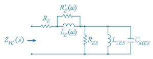
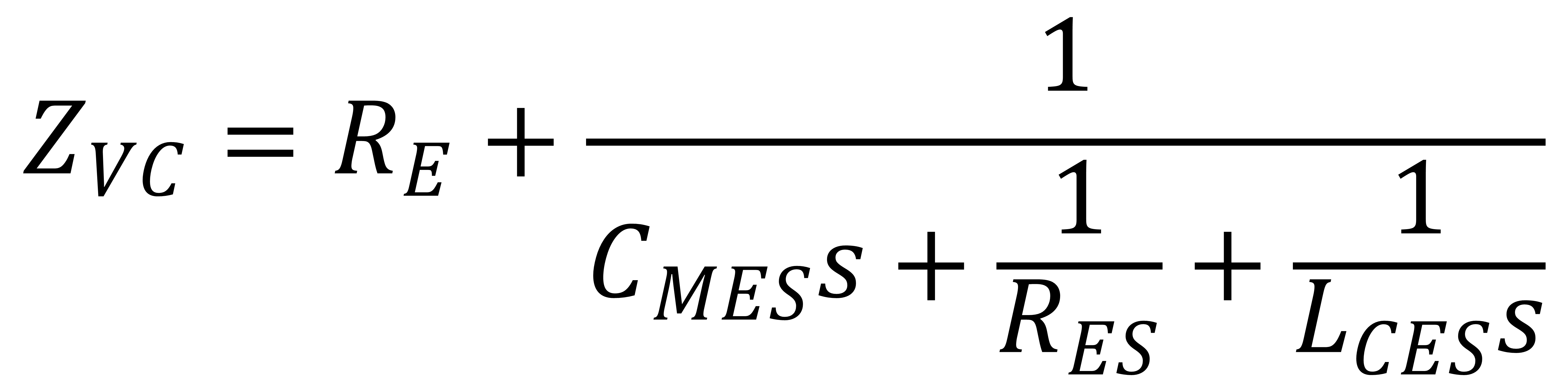
In practical we let ![]() approach positive infinity, so we reduce
approach positive infinity, so we reduce![]() to , rendering in series with
to , rendering in series with ![]() .
.
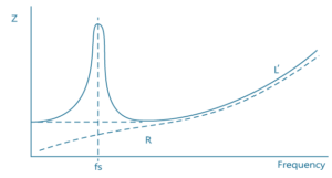
RE is DC resistance and it forms the minimum of the impedance curve, sort of like the absolute value of the foundation. At 0hz, i.e. DC, this value can be measured.
In low frequencies especially below the impedance peak, we can safely ignore the inductive effects of LE(ω). Now the dominating factor is the motional impedance, valued at ![]() . This rationalizes the peak around the resonance frequency in the impedance curve. If we clamp the diaphragm from moving, we’ll instead measure a blocked impedance without such peak. This motional impedance arises from the interaction between a capacitive and inductance component, and in reality an extra resistance component to form a damped response. Before the resonance point, the inductance increases and dominates, right after the resonance the dominance quickly shifts to the capacitance with capacitance reaching its maximum and gradually decreasing. At the peak, the inductance equals capacitance and they both cancel due to opposite phase. That is,
. This rationalizes the peak around the resonance frequency in the impedance curve. If we clamp the diaphragm from moving, we’ll instead measure a blocked impedance without such peak. This motional impedance arises from the interaction between a capacitive and inductance component, and in reality an extra resistance component to form a damped response. Before the resonance point, the inductance increases and dominates, right after the resonance the dominance quickly shifts to the capacitance with capacitance reaching its maximum and gradually decreasing. At the peak, the inductance equals capacitance and they both cancel due to opposite phase. That is, ![]() and
and ![]() disappears, leaving only RES in effect, rendering the motional impedance
disappears, leaving only RES in effect, rendering the motional impedance 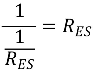 .
.
This is well related to the concept of resonance. At resonance point, energy bounces back and forth between capacitive and inductive elements, without actually being consumed. By doing virtual work, the energy is consumed only by any resistance component such as the damper in the vibration system.
At fs, the total impedance includes the DC resistance along with the motion impedance, i.e. RE + RES, ignoring LE(ω).
 creates a peak around fs, similar to what a bandpass system looks like.
 ![]() ;
; ![]() ;
; ![]() , the equation can be rewritten as below.
, the equation can be rewritten as below.
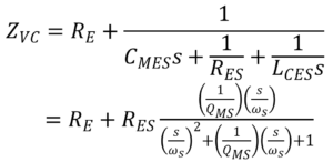
It’s obvious that 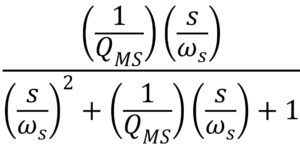 is a transfer function that performs bandpass function according to the angular frequency, s. Apart from this, as the frequency rises we can no longer omit the effect of . As we put that into the equation, we can now explain why the response is tilting upside in higher frequency. This is due to the increased inductive impedance of the coil when frequency rises.
In higher frequency, the motional impedance no longer plays a role. Instead, we still have RE in the bottom and the ever-rising LE. Now we go back to the total equation and focus LE instead of RES、LCES、CMES、RE、RE’. In some cases, LE can be approximated to the following equation.
![]()
This equation is quite complicated so the ne is usually assumed 1 to make it simpler. Only when ne equals 1 we have the power of ω as zero. In this case, LE’s unit is Henry, the usual inductor unit. However, when the ne isn’t 1, then the unit is a variation of Henry.
To conclude, the ups and downs of the impedance curve mainly stems from ![]() and
and ![]() . While the former is due to the inductance of the coil, the latter as motional impedance is due to the Back Electro Motive Force (BEMF). According to Lenz’s Law, a working motor will induce BEMF. As the conducted coil moves up and down in a magnetic field, its material naturally produces a counteracting force, BEMF, to disobey the force thrusted upon by the magnetic field. The direction of BEMF is opposite to the direction of the original voltage, hence reducing the current.
. While the former is due to the inductance of the coil, the latter as motional impedance is due to the Back Electro Motive Force (BEMF). According to Lenz’s Law, a working motor will induce BEMF. As the conducted coil moves up and down in a magnetic field, its material naturally produces a counteracting force, BEMF, to disobey the force thrusted upon by the magnetic field. The direction of BEMF is opposite to the direction of the original voltage, hence reducing the current.
For a dynamic speaker,
- Let BEMF be Vbemf and input voltaeg Vsupply. Considering the effect of BEMF, the current going through the coil,
 . The measured impedance value is now
  . The impedance should reach its maximum at the peak, and considering the input voltage is ideally Vsupply, this means we’d find a minimized current at the resonance point, and to achieve that we need Vbemf to reach its maximum value.
 - BEMF is related to the variability of the magnetic field. The faster the magnetic field changes, the strong the BEMF. It means that the BEMF peaks when the coil and diaphragm move at their fastest speed. Refer to the motor’s equation
 , N is the rotating speed of the motor.
 - Please note that the diaphragm and coil move fastest at fs, so BEMF peaks and the total impedance peaks as well. Keeping this in mind we can figure out the fs with prior knowledge of other T/S parameters.
Electrical Parameters | |||
Re | 7.47 | Ohm | electrical voice coil resistance at DC |
Le | 0.040 | mH | frequency independent part of voice coil inductance |
L2 | 0.003 | mH | para-inductance of voice coil |
R2 | 0.24 | Ohm | electrical resistance due to eddy current losses |
Cmes | 282.27 | μF | electrical capacitance representing moving mass |
Lces | 0.17 | mH | electrical inductance representing driver compliance |
Res | 1.72 | Ohm | resistance due to mechanical losses |
Mechanical Parameters | |||
(using laser) | |||
Mms | 0.084 | g | mechanical mass of driver diaphragm assembly including air load and voice coil |
Mmd (Sd) | 0.083 | g | mechanical mass of voice coil and diaphragm without air load |
Rms | 0.173 | kg/s | mechanical resistance of total-driver losses |
Cms | 0.587 | mm/N | mechanical compliance of driver suspension |
Kms | 1.70 | N/mm | mechanical stiffness of driver suspension |
Bl | 0.545 | N/A | force factor (Bl product) |
Lambda s | 0.274 | suspension creep factor | |
Loss factors | |||
Qtp | 1.778 | total Q-factor considering all losses | |
Qms | 2.187 | mechanical Q-factor of driver in free air considering Rms only | |
Qes | 9.499 | electrical Q-factor of driver in free air considering Re only | |
Qts | 1.778 | total Q-factor considering Re and Rms only | |
Other Parameters | |||
Vas | 0.0010 | l | equivalent air volume of suspension |
n0 | 0.004 | % | reference efficiency (2 pi-radiation using Re) |
The driver’s fs equals to 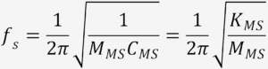 .
.
Mind the units when calculating. In the table, the default unit of MMS is g, while that of CMS is mm/N. Here’s a breakdown below,
- N represents force, described by F=Ma. Its unit should be mass multiplied by acceleration. Mass in kg unit and acceleration in m/ s2
- To cancel out the unit, MMS is transformed into kg value, such that MMS’=0.084*0.001=8.4*10-5kg
- The unit of CMS, mm, should be turned into m, such that CMS’=0.587*0.001=5.87*10-4 m/N
- Finally, it will be

KMS is the reciprocal of CMS, where K is the stiffness, as we recall Hooke’s Law: F=(-kx). On the other hand, C is mechanical compliance. From the above result we deduce some principles of customization.
- To further lower fs, the diaphragm should be softer (via design of material and convolution), and the suspension (including spider) should be softer as well. It will then facilitate enough flexibility for the diaphragm to move freely. Softness implies a much less K value, in essence a higher C value.
- To lower the fs, we can also increase the mass, either by adding thickness or changing material, and most importantly by enlarging the vibration area. A bigger diaphragm as a result will also improve sound pressure level, assuming the power is sufficient. Larger area also increases the added air load.
- There’re lots of tweeters where we see small and thin diaphragms, and the material is hard and crisp. The hardness is sometimes achieved by plating metal element or using glass material. Restricting the surface area is to reduce mass, and the rigidity of the diaphragm is to lift K and decrease C.
Since ![]() , we can know RE= 7.47 ohm, and now the critical factor is
, we can know RE= 7.47 ohm, and now the critical factor is ![]() . Although afterwards we will realize this can be omit, realizing the RES value. Nonetheless, now the capacitive unit is μF, so this value has to be multiplied by 10-6; the inductive unit is mH, so the value should be multiplied by 10-3.
. Although afterwards we will realize this can be omit, realizing the RES value. Nonetheless, now the capacitive unit is μF, so this value has to be multiplied by 10-6; the inductive unit is mH, so the value should be multiplied by 10-3.
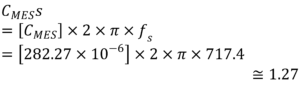
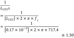
The capacitive 1.27 ohm and the inductive 1.30 ohm cancel out each other in magnitude, due to opposite phase. This means that before the calculation, we actually can omit the two values. Please note that the complex impedance ![]() , so it saves some effort. The resonance frequency is decided by the capacitive and inductive element, while the resonance magnitude is decided partly by the resistive element. The resistive element in this case is RES, leaving
, so it saves some effort. The resonance frequency is decided by the capacitive and inductive element, while the resonance magnitude is decided partly by the resistive element. The resistive element in this case is RES, leaving ![]() reduced to
reduced to ![]() =RES.
=RES.
A complete calculation of impedance is possible, knowing that ![]() . 1.30- 1.27= 0.03.
. 1.30- 1.27= 0.03. 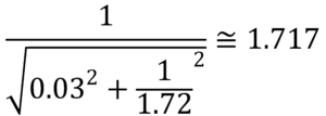 . Please note that 1.717 is not far away from 1.72, and we suppose the negligible difference, 0.003, is simply due to rounding error.
- We have assumed at fs, the LE can be omitted because the value is small. Assuming
 , we get
  . But at higher frequencies this low frequency assumption is no longer valid and we have to use the complete form as .
But at higher frequencies this low frequency assumption is no longer valid and we have to use the complete form as ![]() . Considering Re= 7.47 and Res=1.72, the total impedance value turns out to be 9.19ohm, roughly 9.2ohm. We have to study the impedance curve because it has a lot to do with the driving circuit and amplifier choose.
. Considering Re= 7.47 and Res=1.72, the total impedance value turns out to be 9.19ohm, roughly 9.2ohm. We have to study the impedance curve because it has a lot to do with the driving circuit and amplifier choose.
Below are some observations.
- Impedance magnitude is always larger than DC resistance, and the latter value stands as the minimum value on the curve.
- The peak of the impedance curve is caused by the motional impedance, which rises from the force encountered by the coil moving in the magnetic field.
- The uptilting curve in higher frequencies is caused by the voice coil’s inductance.
- The motional impedance only exists when the diaphragm is allowed to move freely (F=0). If we block the movement then the blocked impedance should be rather flat around the original fs
- There’re many ways to define working impedance, some as DC resistance, some as the minimum value right after the resonance peak, some as the average over a specified working bandwidth.