AATC provides Electret Condenser Microphones (ECMs) and Micro-Electro-Mechanical Systems (MEMS) microphones. Below is a brief introduction.
 ECM consists of a conductive back plate and a front diaphragm. In between sits an insulative gasket ring. The diaphragm sometimes serves as a movable electret plate, often made of metalized polymers or super thin metal films. The back plate is also an electret. The ECM works by imposing a DC voltage across the front and the back plate, forming a capacitor in between. The capacitor (C) equation shows Q=CV, where Q is the charge and V is voltage. Please note that
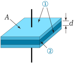
 ![]() , where ε is the dielectric constant, A is the relative area between the two plates, and d is the distance between the two plates.
, where ε is the dielectric constant, A is the relative area between the two plates, and d is the distance between the two plates.
The movement of the diaphragm changes the capacitance of the device and thus changes the voltage across the capacitor. This brings a change in the output voltage across the load resistor, often 2.2kohms. As the sound wave encounters the diaphragm, the diaphragm is pushed and the distance between the plate, d, changes. This creates a slight fluctuation in the capacitance. Assuming constant Q, V is then proportional to d.
Since the capacitor impedance is high in the audio bandwidth, often in 10~15M ohms, so it’s very difficult for the charge to leak out. It means that the charge Q can be considered fixed. As the voltage changes, a potential difference is incurred, and the mic produces a corresponding signal. Since the capacitance in the ECM is small, this means that the charge is small as well. To magnify the signal we put a amplifier in the ECM, usually a Junction-gate Field-Effect Transistor (JFET) component, to form a output impedance low enough for the microphone. To ensure constant voltage, we need to put a resistor of high value in series.
The ECM that AATC provides is pre-polarized, which means that no polarizing voltage is needed when we operate the ECM. Although the charge on the electret may gradually float away, it leads a lifespan of at least 20~30 years. On the opposite, some microphones used in studio or measurement labs aren’t pre-polarized. This means that it always operates on an external DC power such as the phantom 48V power. Note that a low voltage input is still required when we’re using ECM, but that isn’t for polarizing. Instead, it’s the Vdd voltage, often 2V, used to supply the amplifier such as JFET.
ECM falls into three categories based on the how the capacitance is formed.
 Foil-type ECM: This is the most common configuration, where the diaphragm is capacitive. We have to strictly control the moving mass as the electret is located on the foil, otherwise higher frequency performance might be compromised. AATC’s AMF series are foil-type ECMs.
- Back-type ECM: The back-type electret is applied on the back plate, leaving the diaphragm free of electret. AATC’s AMB series are back type ECMs.
- Front-type ECM: Front-type microphones remove their back plates, leaving only the back of the microphone chambers. The electret is attached on the back of the diaphragm.
 Foil-type ECM: This is the most common configuration, where the diaphragm is capacitive. We have to strictly control the moving mass as the electret is located on the foil, otherwise higher frequency performance might be compromised. AATC’s AMF series are foil-type ECMs.
To avoid the charge sneaking away, the output impedance of this capacitive element is set very high. To match such high impedance to external circuit, we need a way to transform the impedance. The JFET plays an important role in reducing the output impedance. After that, the voltage signal is sent to the next device, often the preamp’s load impedance. The output impedance value can be between 1/10 and 1/5 of the load impedance.
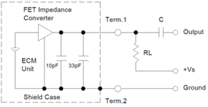
The internal circuit of a typical ECM is shown below: the 10pF and 33pF capacitors in parallel function to eliminate the switching noise of the Global System for Mobile Communication (GSM) frequency. The capacitor at the output port is used to remove the DC portion of signal, as the DC of Vs might interfere with it. RL resistor is the bias resistor for the JFET to be in its working position, usually valued at 2.2kohms. This is why many ECM’s output impedance is 2.2kohms. Vs is usually 2V for ECM and 1.8V for MEMS microphones.
In the manufacturing process, electrons collide with the diaphragm under high temperature and high pressure, creating positive and negative charges on the two surfaces respectively. This film with stored charges is called electret. At present, the most used material is Fluorinated Ethylene Propylene (FEP) electret, whose charge density is high. It’s also stable and stands high temperature. In earlier times, electrets were made of inorganic materials, such as Brazilian palm wax and sulfur, but their use was greatly limited by their large size, low charge storage and short life span. In 1962, Bell Laboratories developed the first electret microphone with a flexible polymer FEP film as a capacitance.
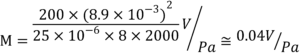
It’s important to minimize the unit-to-unit variability of frequency response variability. The sensitivity of each microphone, under some assumptions, can be simplified as follows.
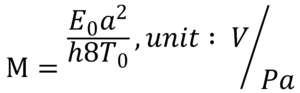
E0 is polarized voltage, a is the diaphragm’s radius in meters, is the distance between the diaphragm and the back plate in meters, and T0 is the effective tension of the diaphragm in N/m. For a measurement microphone with a diameter of 25mm, common values are:
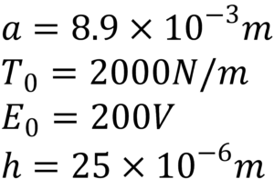
So we can know below answer.
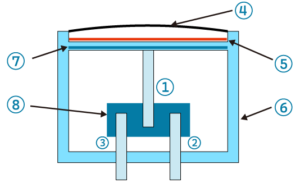
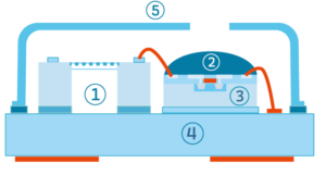
Apart from ECM, MEMS microphones are gaining popularity in some 3C products including mobile phones, tables, laptops and smart speakers. The MEMS microphone market was once dominated by Knowles, but as its patent expired, more competitors entered the market. AATC is the distributor for Merry’s MEMS microphone in Taiwan. Merry’s products has the quality of Knowles but the price competency of Asian manufacturers. MEMS microphones can be divided into top port and bottom port type, based on their port location. The internal structure is shown below.
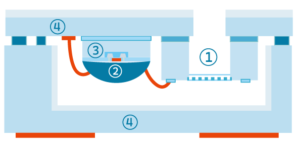
The main difference between top and bottom port is as below.
- The front volume of a bottom port microphone is much less than that of a top port, which means the upper resonant peak of the whole package is pushed high. The value surpasses 20khz and can reach as high as 40khz, which ensures a flat response in the working bandwidth. Moreover, thanks to its relatively large back volume, the bottom port microphone boasts a good low frequency response.
- In the SMT process, the downward-facing sound port prevents itself from damage when the nozzle picks up the upper surface of the microphone. The nozzle creates a huge and rapid pressure change, and it can harm the diaphragm if it touches the sound port in a top port microphone. Hence, the assembly risk for bottom port microphone is much less.
- With regards to bottom port microphones, perfect air-tightness should be ensured between the MEMS PCB and the main PCB in the final product. Failure to seal airtight would invite unrelated noise in the signal.
- The sound port of a bottom port microphone can often connect itself directly to the outside environment. On the other hand, for a top port microphone, a longer sound tube may be required to guide the incoming sound. Long sound tube might cause Helmholtz resonance and subsequently a peak in mid-to-higher frequencies.
- SNR of bottom port microphones are usually higher.
Here comes an important parameter, which is directivity. We use a very simplified figure to explore how directivity is formed: Take bidirectional microphone as example, when sound travels to the front of the microphone, it will first hit the front diaphragm. After a time delay, Δ t, it will arrive at the back of the diaphragm. The resulting pressure gradient moves the diaphragm. 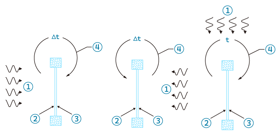
When a sound wave comes from behind, there’s also a time difference, T, after which the wave meets the front of the diaphragm. This also propels the diaphragm to move. But when the sound waves arrive from the sides, they spend about the same amount of time to reach the front and back of the diaphragm, so the pressures on the front and back cancel each other out, leaving almost no pressure difference. The diaphragm therefore does not vibrate, making the sides of the bidirectional microphone very sensitive to sound.
With regard to the cardioid microphones, the sound wave from the front has to travel far to the back, turn around, and circle back into the microphone capsule. The time difference also causes the diaphragm to vibrate, which forms the uni-directionality.
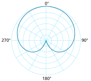
Then, the sound from the back reaches the back and front of the diaphragm almost at the same time, creating literally no delay. This means that the pressure gradient is small, barely moving the diaphragm. However, the sound coming from the sides reaches the front and the back with a time difference. This is why cardioid microphones are sensitive to side sounds. As the sound source moves to the back, sensitivity decreases rapidly.
A shotgun microphone is the kind you would see in a fancy conference room. A boom mic seen in a TV or movie record setting also uses a shotgun. It hardly receives sound from the sides, but only the sound coming from the front.
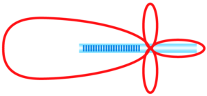 The idea is to add a long interference tube in front of the microphone diaphragm. This interference tube allows the sound coming in from different directions to reach the diaphragm in different ways: the sound coming in from the front reaches the diaphragm only through the front inlet on the interference tube, so it travels directly to the diaphragm, captured by the diaphragm. The sound on the sides goes through the interference tube, changing its phase and offsetting each other. In this way, side sounds create merely no air pressure when it reaches the diaphragm.

Effects of different directional microphones are shown as follows.
- Mediu- range omnidirectional microphone is suitable for medium-range sound source.
- Close-range recording utilizes the proximity effect to compensate some bass frequency loss. When the performer thinks the recording lacks bass, approaching nearer the microphone can help, as it will lift bass response. Mind that downside that if the distance is too close, too much bass frequency can cause muddy sounds.
- The frequency response of unidirectional microphone is very important. The user holding the microphone usually doesn’t always direct the mouth directly, and doesn’t keep it aligned to the middle of the diaphragm at all times. Usually the mouth is within a 45 degrees off-axis area. So it’s important to have unidirectional microphones to tolerate this variability in usage.
- Due to the lack of natural ambient sound, the recording of the shotgun microphone is dry. It can be used to suppress the sound of nearby instruments or background conversation
- Wider directionality can take more side sounds or enhance low frequency reception
- Omnidirectional microphones are used to naturally capture ambient sounds, but the directionality will narrow with the higher frequency. Only one side of the diaphragm is exposed to the air for this kind of microphone. It should be noted that when the wavelength of the measured frequency is less than the diameter of the diaphragm, omnidirectionality can turn into unidirectionality. This is because the high-frequency waves have a hard time diffracting and traveling around the whole diaphragm.
Narrow directionality can also avoid echo, because it can be designed to receive from a target sound source, but not the sound of the nearside speaker.
