AATC can recommend the most suitable geometric designs for the rear cavity, front cavity, sound holes, and channels to optimize the overall performance of the acoustic system.
The customer’s product will include an acoustic cavity where the speaker is installed. The space in front of the speaker is called the front cavity, and the space behind it is called the rear cavity. Typically, the volume of the rear cavity affects the low-frequency performance, while the volume of the front cavity influences high-frequency performance. The design of the front and rear cavities is crucial to the acoustic system, as the frequency response curve is influenced by the volume and even the geometry of the cavities.
Speaker cavity design involves five aspects: the front cavity, rear cavity, sound outlet, dustproof mesh, and sealing. Each aspect has its specific function. The typical structure of an acoustic cavity is shown in the diagram on the right.
- Restrict the propagation path of sound behind the speaker to prevent mid- and low-frequency sounds from interfering with sounds in the front, avoiding the phenomenon of acoustic short circuit. This enhances the mid- and low-frequency response, making the low frequencies richer and fuller.
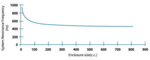
- The larger the rear cavity, the lower the system’s overall low-frequency extension. However, volume increase has a saturation effect; once it exceeds a certain volume, further low-frequency improvements become minimal. For example, with a 36mm diameter speaker from AATC, if the rear cavity volume exceeds 40-60 c.c., the product’s low-frequency resonance approaches approximately 500 Hz.
- If the rear cavity is inadvertently designed into certain geometrical shapes, it may create standing waves, causing unwanted resonance at certain frequencies. To avoid standing waves in the rear cavity, it is recommended to avoid overly symmetrical designs or narrow and elongated cavity shapes.
- The front cavity limits the high-frequency extension of the product.The advantage is that it can reduce some high-frequency noise, such as frequencies above 10kHz. However, the drawback is that it also limits the mid-to-high-frequency performance of the product, potentially causing acoustic resonance at cutoff frequencies between 6–10kHz, leading to uneven frequency responses.
- The front cavity should be as small as possible. If the front cavity is too large, it can easily lower the high-frequency cutoff, reducing the bandwidth of the mid-to-high frequencies. In addition to keeping the cavity small, the opening area of the front cavity should also be as large as possible. If there is a duct in the front cavity, the duct should be as short as possible. The opening area and the front cavity must maintain a certain ratio; the larger the cavity, the larger the opening area needs to be.
The front cavity must at least accommodate enough space for diaphragm movement, to prevent the speaker’s excessive amplitude from causing the diaphragm to strike the product casing, resulting in interference and noise. AATC can recommend different front cavity distances based on various speaker units.
Speaker amplitude (XD):

Parameter egstands for input voltage, VAS is equivalent compliance, ρ0 is air density, c is sound of spee, SD is effective diaphragm area, ωs equals to 2πfs which is resonant angular frequency, QES is electrical Q factor, s is the variable of angular frequency, while QTS is the total Q factor.
 Note that
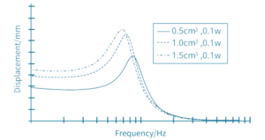
  is essentially a transfer function, in which is s is the variable and ω_s is a parameter. This function behaves as a low-pass filter, describing the relationship between diaphragm displacement and frequency. The excursion is the largest in the low frequency band, and above the cutoff frequency the magnitude drops dramatically. The front volume should not obstruct any diaphragm movement. The larger the back volume, the more compliant the air movement is, hence boosting the excursion. This warrants careful attention. The figure below shows how a 0.1W-rated speaker sees its displacement increase as the back volume grows from 0.5cm3 to 1.5cm3.
The Q factor of a speaker (Q, short for Quality) primarily refers to the total quality factor, QTS. The total quality factor is the reciprocal of the parallel combination of the electrical quality factor (QES) and the mechanical quality factor (QMS): ![]() .Based on
.Based on ![]() , the larger the QTS, the larger the excursion, XD. The effect is most prominent when , which means the excursion reaches its maximum when s/ωs=1. Other factors like the input voltage, eg, and the coil DC resistance, RE, is positively related to excursion. With regard to SD, as this value gets bigger, it means that the same force is distributed on more area, reducing the displacement per area. Furthermore, VAS is the equivalent compliance. It expresses the volume of air that when compressed to one cubic meter (or any other volume unit) exerts the same force as the compliance (Cms) of the suspension in a particular speaker. By definition, , while Cms is the softness of the surround and spider system. We observe that the softer this surround and spider system is, the more compressibility of the air, hence the more room and flexibility for the diaphragm.
, the larger the QTS, the larger the excursion, XD. The effect is most prominent when , which means the excursion reaches its maximum when s/ωs=1. Other factors like the input voltage, eg, and the coil DC resistance, RE, is positively related to excursion. With regard to SD, as this value gets bigger, it means that the same force is distributed on more area, reducing the displacement per area. Furthermore, VAS is the equivalent compliance. It expresses the volume of air that when compressed to one cubic meter (or any other volume unit) exerts the same force as the compliance (Cms) of the suspension in a particular speaker. By definition, , while Cms is the softness of the surround and spider system. We observe that the softer this surround and spider system is, the more compressibility of the air, hence the more room and flexibility for the diaphragm.
It shows that the diaphragm displacement is closely related to the performance factors of an acoustic system.
- The higher the input voltage, the larger the displacement
- The softness of the diaphragm, surround and spider is negatively related to displacement
- The smaller the enclosure, the smaller the displacement
- The larger the DC resistance, the more energy is dissipated on the coil, hence the less driving energy and the less the displacement.
- The back volume encompasses the back of the speaker and prevents the back sound wave from traveling to the front. When the sound from the back, often anti-phase to the front, leaks to the front, it may cause acoustic short circuit. This describes the back soundwave cancelling out the front waves, severely decreasing the front sound pressure level. By containing soundwaves in the back volume, back enclosure designs can enhance mid to lower frequency performance.
- The larger the back volume, the lower the cutoff frequency can extend. However, diminishing return will occur as the volume continues to rise. That is, one cannot endlessly decrease resonant frequency just by increasing the volume to, say infinity. The following example shows the frequency calculation of a phi 36mm speaker that AATC produces. From it we observe that as we approach 40 to 60 c.c. in terms of volume, we seem to approach a minimum point of 500hz resonant frequency.
- The back enclosure might show signs of standing wave if it is designed improperly. Standing waves might cause resonance vibration at certain frequencies, which give rise to noise. To avoid it, it’s recommended to design asymmetrical geometry and the space shouldn’t be too narrow or long.