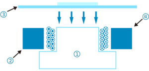
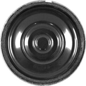
A magnetic buzzer includes a silicon steel, magnet, voice coil and T-shaped soft iron in the housing. Driven by V0p electrical signal, the silicon steel as diaphragm vibrates inside and produces sound, due to electromagnetic effect. The signal V0p means that the diaphragm is attracted downwards during HI, and it reverts to its original position during LO, that is, absent of any excitation. The stronger the magnet and the more the coil rounds, the higher the Sound Pressure Level (SPL). The diaphragm of the magnetic buzzer has to sit firmly on a physical step. There are three kinds of steps, one formed by ferrite and plastic housing; another formed by plastic magnet; the other consisting of ferrite and metal ring.
The diaphragm movement is affected by the diaphragm mass, coil length and height, magnetic material and the material of metal ring.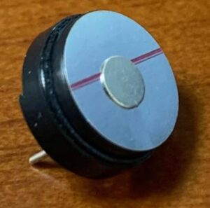
Piezo buzzer’s ceramic, piezoelectric diaphragm is glued and attached to the housing. Due to piezoelectric effect, the diaphragm moves up and down when input alternating Vpp signal.
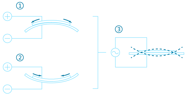
There’re several ways to fixate a piezo plate, and each has different sound effects. The two main methods are “edge support/ circumference fixing” method, and the other one is “node support/ nodal mounting” method.


The sound performance is affected by the dielectric constant, thickness of the piezo plate, along with the sizes of the buzzer’s front and back chamber, and the geometry of the front sound hole.
A magnetic buzzer’s working principle is similar to dynamic speakers, both driven by electromagnetic forces. The difference is that the coil doesn’t move in buzzers: the diaphragm itself is conductive and attracted to the electrically magnetized coil. So diaphragm is attracted and starts moving, and it’s not the coil that moves. On the other hand for speakers, the diaphragm and voice coil are glued together and thus they move up and down in the magnetic field as a whole. There’re indeed some magnetic-motor-elements that are fixated and still in both buzzers and speakers, which for example are the yoke and magnet.

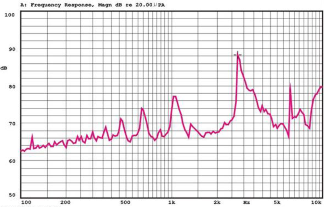
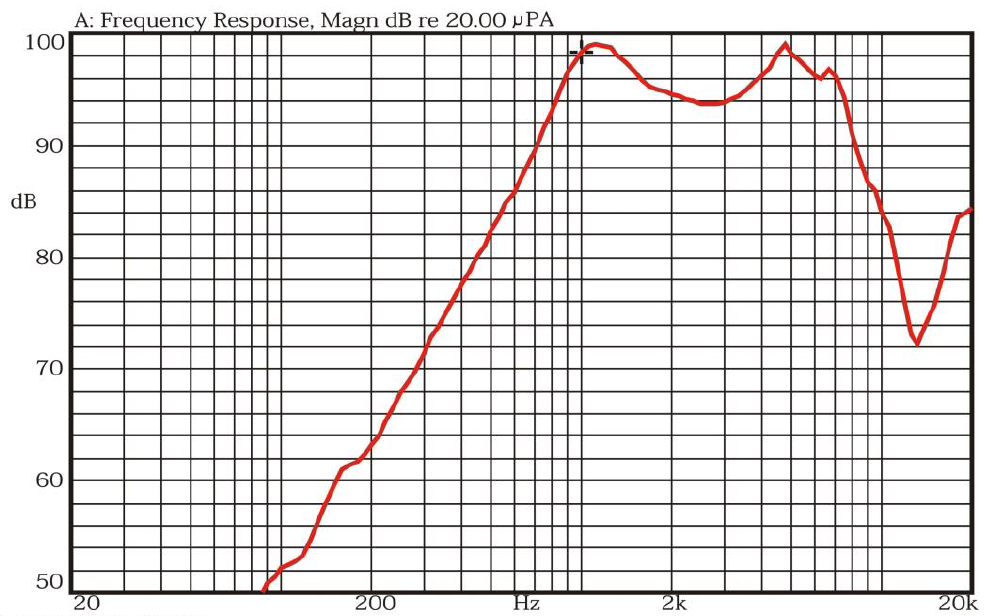
Magnetic buzzers are suitable for playing out 2khz~4khz sound, especially between 2,400hz and 2,730hz. The human ear is mostly sensitive to this bandwidth due to the resonance effect of the eardrum length. There’re both top port and side port buzzers, and the choice depends on the application. Usually top port buzzers are preferred, while side port buzzers are usually used in products that have very narrow and short gaps, which the buzzer is tucked in. The main PCBA and buzzer are placed in the thin gap, forcing the sound hole to be on the side, to avoid it being obstructed. Piezo buzzers are more suitable for higher-pitched frequencies, such as 4khz beeps. Frequencies between 3khz and 4khz has a more alerting nature, so piezo buzzers are sometimes used as alarms or horns. The reason why piezo buzzers are suitable for higher frequencies is that their diaphragm and piezo plates have higher rigidity and thus increase the resonant frequency. Also, piezo buzzers are usually shaped like flat plates, which have acoustic effects of raising the resonance peaks higher.
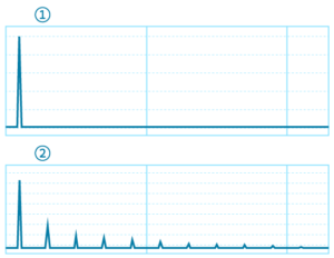
Furthermore, buzzers are usually input square waves, which includes a fair amount of harmonics related to its buzzing, alarming nature. On the other hand, speakers are tested using sine waves, while in real world speakers play out a wide variety of complicated signals, including voice and music.
It’s possible to control the volume by tweaking the duty cycle of the buzzer. Take magnetic buzzer for example, the higher the proportion of LO cycle, the smaller the volume. As for piezo buzzers, duty cycles are manipulated to control the proportion of several orders of harmonic waves, to change the SPL and tone nature.
NO / Duty | Hi 50% / Low 50% | Hi 25% / Low 75% | Hi 10% / Low 90% | Hi 5% / Low 95% |
NO.1 (dB) | 90 | 87.6 | 80.4 | 67.8 |
NO.2 (dB) | 93 | 90.3 | 83.1 | 71.2 |
NO.3 (dB) | 92.5 | 90.2 | 83 | 70.3 |
Buzzers aren’t used to play low frequencies. The first reason is that low frequency doesn’t sound alerting but dull and boring, which makes the buzzer useless. The second reason is that the diaphragms in buzzers are either steel silicon or ceramic, and these kinds of hard materials have very high resonant frequencies. Buzzers create very little sound below the resonant frequency due to the rapid frequency roll-off.
If one wants to play out voice or music, then speakers must be used because the speakers’ diaphragms are much softer. Furthermore, the bandwidth of a buzzer is very narrow because its Q value (inversely proportional to damper) is quite high. It’s designed to be like this because a buzzer by default only emits sounds at its resonance peak, not at other unrelated frequencies. The speaker instead focuses on a wider bandwidth because human voice and music signals are broadband, so the diaphragm must exhibit lower Q value to flatten out the frequency response.
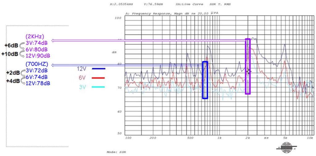
Magnetic buzzers are said to be current-driven, because the silicon steel is sensitive to current instead of voltage. The higher the input current, the higher the SPL. This is because the working mechanism, electromagnetic force (Bli) focuses on current (i). Yet some buzzers can still produce enough SPL, for example 70dB or 75dB, when input a mere 1.5V signal. Operating working voltage ranges for magnetic buzzers are typically narrow, usually in 5V range. If input maxes out, the SPL will quickly reach its saturated point which can bring damage. Since magnetic buzzer is driven by electromagnetic force and it has high resistance (reminder: there’s coil), so its current consumption is high, often in the 40mA to 150mA range. The consumption value depends on the Q value of the coil inductance and the strength of back electromagnetic force (bemf). The higher the bemf, the lower the current at its resonant peak.
The ceramic plate in piezo buzzer is sensitive to voltage instead of current, so it’s said to be voltage-driven. The higher the input voltage, the higher the SPL. It usually takes a minimum of 3V to let a piezo buzzer produce enough SPL. Fortunately, piezo buzzers can tolerate high voltage usually up to 20V or 30V, so there’s plenty of room of SPL increase.
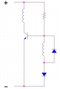
Some alarms play out complicated multi-tones, with the tones already designed in the oscillation circuit inside the alarm. This kind of alarms operate on DC power. Piezo alarms are essentially capacitive elements so the impedance is quite high, which implies that the current consumption is quite low, low as 10mA or even 1mA. Due to its power-saving nature, piezo buzzers are commonly used in portable devices which run solely on battery. A reminder for driving a piezo buzzer is that a resistor in parallel should be added, because the resistor allows for proper charging and discharging of the piezo plates. This is different from magnetic buzzers, which usually need a diode to maintain proper up-and-down movements.
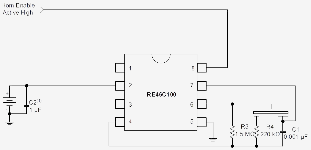
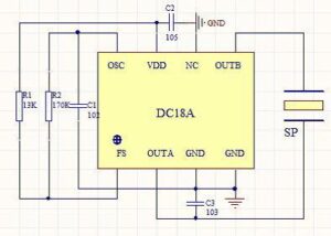
If the buzzer includes oscillation circuit, then it’s called internally-driven buzzers, or indicator buzzers. If not, then it’s called externally driven buzzers, or transducer buzzers. Transducers allow for greater design flexibility as the user can decide the signal frequency by an external oscillation circuit not included in the buzzer. However, the user-defined frequency is still suggested to be set around the resonance frequency to produce maximal SPL. On the other hand, the frequency output of an indicator is already fixed by its built-in oscillation circuit. The advantage is its ease of use, as it can be directly plugged in a DC source and play back sound instantly. Below are some examples of oscillation circuits used in AATC buzzers. Indicators usually have epoxy covering the PCB board to prevent board damage. Also, due to the limits of the oscillation IC’s input voltage, the working input voltage range is narrower than a transducer.
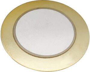
Piezo transducers, i.e. externally-driven piezo buzzers, usually use the edge support type; by contrast, the piezo indicators, i.e. externally-driven piezo buzzers, use the node support type. In the node support mode, the contact area between the plate and the housing is limited to the rim of the ceramic plate, the inner circle of the piezo plate. Alternatively, the edge support’s contact area is the rim of the brass plate, the outer circle of the piezo plate.
The vibration mode in the case of node support is called the bending mode, which is the natural vibration pattern, i.e. free-state, of a piezo plate when no external force applies. The rim of ceramic plate as nodes stays still while the other part vibrates back and forth. The advantage of edge support node is that the energy transfer efficiency is high enough so the SPL is high. It’s often used in indicators because this mode naturally only occurs at one frequency, which can be arbitrarily set at the working frequency of this indicator. Note that an indicator generally only plays out one pre-determined frequency. Also, because the node doesn’t move, so this fixing method is stabler and the gluing of the plate is easier.
Edge support mode connects the outer rim of the whole plate to the housing. This vibration mode suppresses the free-state bending mode, and thus the fundamental resonant frequency. Due to suppression, the SPL is lower compared to node support node. But the advantage is that these kinds of buzzes have lower Q value and a wider bandwidth. Hence, it’s most commonly used in transducers, where the user is allowed to input a wide variety of signal frequencies. By relying on this mode, the user won’t sacrifice much SPL if the input frequency doesn’t equal to the buzzer’s resonate frequency.
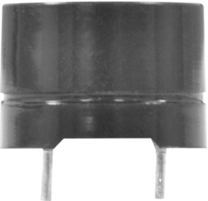
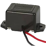
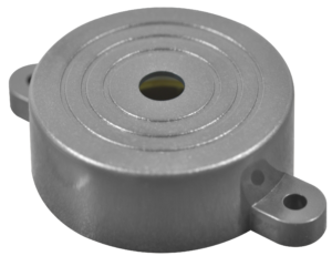 Termination for magnetic buzzers are usually PIN-type or SMD-type, seldom being WIRE-type. Magnetic buzzers are best situated on any horizontal plane or products standing still. Termination for piezo buzzers are usually PIN or WIRE, seldom being SMD. The advantage for coming with a wire is the flexibility to place the buzzer further away from the main PCB board, nearer the product surface. Piezo buzzers are robust to shocks and vibrations, so that it can be placed in hazardous or even vertical, upside-down product applications. Some larger buzzers have lock holes and some holes are even oval ones to allow for mechanical assembly tolerance.
There’s also a kind of buzzer called mechanical buzzers. It entered the market a very long time ago and the sound frequency is usually 60hz or 400hz, similar to the frequency of mains electric and typical motor speed. The playback sound is rougher and coarser than magnetic or piezo buzzers, so it hasn’t prevail. The advantage is that it’s easy to control. For example, it can be driven simply by a 110V or 220V mains power source, or 12V or 24V automobile battery source, no need for any external circuit.