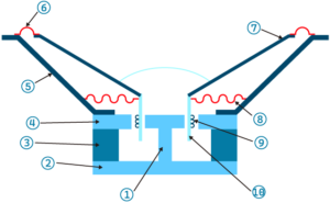
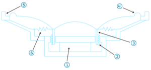
There’re two different structures of speakers, inner-magnet and outer-magnet ones. By definition, inner-magnet speaker has its magnet inside the perimeter of the coil, while outer-magnet speaker has its magnet outside of the coil. For inner ones, we make full use of the magnetic field of the magnet, so the advantage is that the flux leakage is relatively small. The magnet of the outer ones is located outside, so there’s relatively no size restrictions. Larger size permits larger and stronger magnetic motor. Even though the flux leakage of the outer one is larger, the driving force is still usually higher than that of the inner ones, because the baseline BL factor is already high enough. Micro-speakers are usually inner ones because of space restrictions, while big loudspeakers for example used in home audio are outer ones.
Usually the smaller the diaphragm, the more suitable for high frequency performance; The larger the diaphragm, the more suitable for low frequency.
- The smaller the diaphragm size is, the smaller the probability of breakup mode, and hence the more stable the higher frequency response.
- The smaller the diaphragm size is, the longer the relative wavelength of the sound wave seems to be, which makes diffraction easier to happen. In order to create a wider sound stage, it’s advisable to maintain a smaller size.
- The larger the diaphragm is, the larger the vibrating mass. So the resonant frequency will be lower, which is suitable for the woofer design.
- The larger the diaphragm is, the larger the added air mass will be, because a large area can move more air. The greater the additional air mass, the greater the system mass, and therefore more suitable for woofer use.
- The larger the diaphragm is, the larger the inertial mass is, thus the greater the driving power required. This is not necessarily an advantage. Therefore, we do not increase the mass of the diaphragm for no reason, except to reduce the resonant frequency of the woofer. Therefore, the size of the tweeter does not have to be large.
- In the low frequencies, the wavelength is large, requiring more volume velocity for a speaker to move enough air. Because of this, woofers need to be large. To attain enough volume velocity, if the displacement falls short, then the force should be compensated by a large enough diaphragm. Increasing the displacement is a dangerous solution, as doing so might add more distortion.
- For the tweeter, the larger the diaphragm is, the greater the sound pressure is. But at the same time, the larger diaphragm will decrease the high cutoff frequency, reducing the bandwidth.
In terms of material, the most common is paper, then some plastic composite such as PET. The sound quality of paper is naturally good, but there’s still room for improvement as it can be post-processed to increase rigidity.
- Carbon fiber can be added to the paper to increase rigidity, widening the high frequency bandwidth. The thickness of the paper fixed, the carbon-fiber-paper combination is lighter, so the sound pressure output is higher. If we can maintain the paper’s advantage of fair damping, the breakup mode of the diaphragm can be inhibited, flattening the overall response.
- In order to improve the E/ρ value of the paper, a layer of beryllium (Be) can be steamed onto the paper surface, where E is Young’s Modulus and ρ is density.
- It’s advised to add in metal materials such as aluminum alloy, in the form of multilayer structure filled with high-damping-ratio resin.
- Use a reinforced foamed metal such as a nickel layer. The density can be small because the porosity can be as high as 98%
- In case of planar speaker, the diaphragm can adopt a honeycomb-like structure to retain damping and rigidity at the same time.
Please see common diaphragm material below.
Material | Property |
PA | PA is a kind of polyester resin with good molding flexibility, and good size and temperature stability. But one disadvantage is that the elastic modulus is low |
PP | PP is a widely used semi-transparent, semi-crystalline thermoplastic polymer with excellent chemical resistance to various chemicals |
PE | PE is the most widely used plastic in industry, generally divided into High Density PolyEthylene (HDPE) and Low Density PolyEthylene (LDPE). HDPE’s melting point, hardness and anti-corrosion chemical resistance are higher than LDPE. |
PS | PS is divided into General Purpose PolyStyrene (GPPS) and High Impact PolyStyrene (HIPS). |
PC | PA, PolyCarbonate refers to bisphenol A polycarbonate, which is the main material of CD turntables. It has good dimensional stability and low water absorption rate. |
LCP | LCP has high elastic coefficient, and can be further enhanced by adding glass fiber or carbon fiber to strengthen the rigidity. In addition, the expansion coefficient of liquid crystal is small, so the dimensional stability is good. Liquid crystal polymer is a multilayer structure, so the internal damping is large. |
PET | PET is a kind of polyester film (mylar), which belongs to thermoplastic plastics and was developed long time before. |
PBT | PBT is a kind of polyester film (mylar), which belongs to thermoplastic plastics and was developed long time before. |
PEN | PEN is an upgraded version of polyester film (mylar). It has low density, high rigidity and higher elastic coefficient than typical mylar. It can resistance high temperature up to 160 degrees Celsius, higher than the 130 degrees resistance of the typical mylar |
PEI | PEI has excellent mechanical properties, electrical insulation properties, radiation resistance, high and low temperature resistance, and cannot be easily worn down. |
PI | PI’s trade name is Kapton, which has higher rigidity and lower mass than typical mylar. But compared with polyester film, PI is more difficult to form, and the price is much more expensive. |
PEEK | PEEK has high strength, high resistance against corrosion, and it’s suitable for machining molding. |
PPS | PPS’s trade name is Deltron, which has good mechanical strength and high rigidity. |
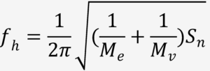
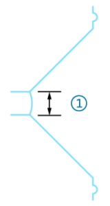
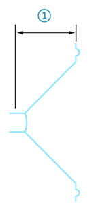
In terms of diaphragm geometry, the narrower the diaphragm angle is, the less likely breakup mode will appear. The breakup mode usually appears at higher frequency, which will disturb the vibration and produce distortion. Therefore, narrow diaphragm angle prevents high frequency disturbance. Setting the upper cutoff frequency of the diaphragm set as fn, the higher the fn, the higher the bandwidth extends. A simplified formula is shown below.
![]()
Me is diaphragm mass, Mv is voice coil mass, Sn is mechanical stiffness, E is the elasticity coefficient, L is the thickness and x is half of the diaphragm angle. We observe that the narrower angle and thicker diaphragms, result in better high frequency response. From the formula we also see the smaller mass increases high cutoff frequency.
It’s hard for a narrow coil to propel the diaphragm. It’s because there’s only such small contact area between the coil and the diaphragm, and the diaphragm will experience disproportionate great force at this area. This might produce distortion and a delay of vibration. As we know, the driving force comes from the voice coil itself, and as the voice coil couples to the diaphragm, we have to make sure the process is fairly linear and free of distortion. Hence, the voice coil has to be wider.
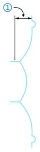
In the case of narrow voice coils, the vibration source is farther away from the diaphragm, which tends to cause phase delay. If the coil gets wider, the vibration source can get closer to the diaphragm, and the force is evenly further distributed on the diaphragm. This means the rigidity gets higher and distortion gets lower. When the coil gets much more narrower, the diaphragm looks more like a dome. The dome is perfectly time-aligned by the coil, so there’s headroom to make the diaphragm thinner, without having to worry lowered rigidity. Also adding more coil can increase the driving force as the “L” factor in BL value increases, which is seen in a wider coil configuration. Yet beware that more coil adds more mass and can risk efficiency loss. So there’s always a compromise and optimization point when designing speakers.
To improve the speaker’s power-handling capacity, the coil diameter has to be increased. A simplified formula shown below might apply.
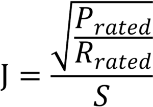
J is the maximal current density of the coil, usually valued at 70 A/mm2 for loudspeakers; Prated as the rated power, Rrated as rated impedance, and S as the cross-sectional area of the coil. Given a 8 ohm speaker, assuming the coil diameter as 0.13mm, cross-sectional area as 0.013mm2, then we can calculate the maximal power Prated as 7W。We need to further increase the diameter if we desire more power rating.